What is PTP?
Precision Time Protocol (PTP), defined in the IEEE1588-2008 standard, is a protocol that uses a master-slave hierarchy to synchronize clocks on network devices. PTP uses hardware time stamping to achieve submicrosecond synchronization. PTP defines how real-time clocks in a network synchronize with each other. A network where PTP operates is called a PTP domain. This protocol operates by organizing clocks within a PTP domain into a master-slave hierarchy. The reference time for the entire system comes from the root clock, also known as the grandmaster clock.
PTP is more accurate than NTP because it uses hardware timestamping. PTP also accounts for device latency while synchronizing time. NTP synchronizes clocks with millisecond accuracy; PTP achieves submicrosecond accuracy.
Best master clock algorithm
PTP uses the best master clock algorithm (BMCA) to compare clocks in a network. BMCA determines the status of ports in the network:
- Master—A clock that provides time to other clocks in the network.
- Slave—A clock that receives time from other clocks in the network.
- Passive—A port that is neither a master not a slave.

Master–Slave Hierarchy in PTP
The protocol primarily organizes the clocks into a master–slave hierarchy based on the Best Master Clock (BMC) algorithm running on each port. The BMC uses a hierarchical selection algorithm based on certain attributes, such as priority, variance, traceability, accuracy, etc., to choose a candidate clock.
How Does PTP Work?

- The actual synchronization process starts after the master–slave hierarchy is established by calculating the link delay (offset) and time difference between the master and slave devices based on timestamps generated when the devices exchange event messages.
- PTP calculates the link delay and time difference between the master and slave devices based on the timestamps generated when the devices exchange event messages. PTP then synchronizes the time and frequency between the master and slave devices.
- Timestamps can be carried in PTP messages in either one-step or two-step mode (will be discussed later in another article).
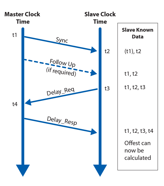
- Master Clock Slave Clock Slave Known t2 The synchronization process is categorized in two distinct phases: In phase 1, the offset time between the master and slave clock is corrected, and in phase 2, the propagation delay between master and slave clock is computed.
- The first phase comprises of the grandmaster clock sending a SYNC message to the slave clocks; and the slave clocks recording the packet arrival time (t2).
- The GMC then sends a follow-up message with the actual timestamp when the first sync message was sent (t1), therefore allowing the slave clocks to exactly calculate the master–slave delay.
- The second phase comprises of the slave clock sending a delay request message to the master (t3). The master clock responds to this message with a delay response message (t4), allowing for the slave clock to determine the slave-master delay.
- At this state, both the clocks are aware of the offset; therefore the ability to calculate the exact propagation delay.
