In this article, I will explain the Beamforming technique in 5G to compensate for path loss especially in the mmWave spectrum range. As the range of mmWaves is between 30 GHz and 300 GHz, a wavelength is between 1 millimeter and 10 millimeters and this is the intensive motive for Beamforming.
Beamforming Definition
The beamforming technique focuses the RF energy into a narrow direction to allow the RF beam to propagate farther in that direction. Using this technique, non-line of sight (NLOS) RF communication in the mmWave spectrum may rely on reflection and/or diffraction of the beams to reach the UE.
If the direction becomes blocked, either because of UE movement or changes in the environment (e.g., obstacles, humidity, rain, etc.), the beam may not be able to reach the UE. Thus, in order to ensure that the UE has continuous, seamless coverage, multiple beams in as many different directions as possible may be available.
Beamforming Types
If the base station is equipped with digital beamforming, the base station may concurrently transmit multiple signals in multiple directions or may receive multiple signals concurrently in multiple directions.
Beamforming Management Operation
There’re 4 operations:
- Beam sweeping: The covering of a spatial area with a set of beams transmitted and received according to prespecified intervals and directions.
- Beam measurement: The evaluation of the quality of the received signal, which can be expressed in terms of Reference Signal Received Power (RSRP), the Reference Signal Received Quality (RSRQ), a measurement that includes also thermal noise and signals from other sources, or the Signal to Interference plus Noise Ratio (SINR).
- Beam determination: the selection of the optimal beam (or set of beams) to set up a directional (and fully beamformed) communication.
- Beam reporting: the procedure with which the nodes send to the RAN information on the quality of the received beamformed signals and on their decision in the beam determination phase.
Beam Sweeping
Beam sweeping: is the first operation of the four of Beam Management operations.
The gNB transmits m beams in different spatial directions. The UE listens/scans for the beam transmissions from the gNB in n different receive spatial directions (a total of m*n scans). Based on the performed beam sweeps, the UE determines a channel quality associated with the performed beam sweeps. Then the UE sends the channel quality information to the gNB.
The channel quality is affected by a variety of factors. The factors include
1- Movement of the UE along a path or due to rotation (e.g., a user holding and/or rotating the UE ).
2- Movement along a path behind obstacles, and movement within particular environmental conditions (e.g., obstacles, rain, humidity).
Also the UE and the gNB exchange other information (e.g., analog or digital beamforming capabilities, beamforming type, timing information, configuration information, etc.).
Based on the received information, the gNB determines various configuration information, such as mmW network access configuration information, information for adjusting beam sweeping periodicity, information regarding overlapping coverage for predicting a handoff to another gNBs.
The measurement process is carried out with an exhaustive search, i.e., both users and base stations have a predefined codebook of directions (each identified by a beamforming vector) that cover the whole angular space and are used sequentially to transmit/receive synchronization and reference signals.
Beam Sweeping Technique
A Beam Set may contain eight different beams. For example as below figure 8 beams for eight directions. The gNB is configured to beamform for transmission of at least one of the beams OR can sweep/transmit directions using eight ports during a synchronization subframe.
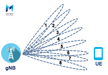
The UE is configured to determine a beam index corresponding to a beam based on a time at which a Beam Reference Signal (BRF) is received.
Beam Measurement
The UE selects a beam by measuring values for a received power or received quality associated with each of the first set of beams, the received power may be referred to as a BRS received power (BRSRP).
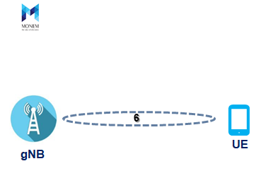
Beam Determination
Here, The UE selects Beam Index (6) as it’s the “Best” beam from the UE point of view (Highest BRSRP).
Beam Reporting
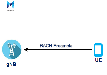
After beam determination, the UE has to wait for the gNB to schedule the RACH opportunity towards the best direction that the UE just determined, for performing random access and informing the selected serving infrastructure of the optimal direction through which it has to steer its beam, in order to be properly aligned.