Functional Split Options for 5G Networks
As network architects work to meet the 5G challenges of increased traffic and data flows, a fundamental question is how much intelligence to put near the antenna versus at the DUs or CUs.
Mobile Network Operators (MNOs) as well as industry-standards groups, such as the 3GPP, IEEE, Telecom Infra Project (TIP), and O-RAN, have been rethinking network architectures.
What does Functional Split mean? That means how the RAN can be disaggregated into distributed components (DU) and centralized components (CU). The 5G RAN has a number of architecture options, such as how to split RAN functions, where to place those functions, and what transport is required to interconnect them.
3GPP Split Options
3GPP has defined 8 functional split options for fronthaul networks in Technical Report 38.801 as below:
- Option 1 (RRC/PCDP)
- Option 2 (PDCP/RLC Split)
- Option 3 (High RLC/Low RLC split, Intra RLC split)
- Option 4 (RLC-MAC split)
- Option 5 (Intra MAC split)
- Option 6 (MAC-PHY split)
- Option 7 (Intra PHY split)
- Option 8 (PHY-RF split)
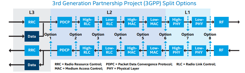
With an option 2 split, for example, some Layer 2 (L2) Ethernet functions can reside in the RRH and there is the possibility that aggregation and statistical multiplexing can be done before the data is passed across the fronthaul network. This greatly reduces the amount of data transmitted across the interface. On the other hand, with an option 7 split, some Layer 1 (L1) functions can reside in the BBU and pooling gains can be realized with centralized processing.
Many fronthaul connections use the Common Public Radio Interface (CPRI) connection protocol, which has been used mainly for point-to-point transport for macro base stations. Because of the increase in the scale of 5G, a more efficient fronthaul interface is needed. As industry bodies consider new network architectures, a key consideration is a functional split that separates layers between the BBU and the RRH.
The basic question is how much compute to put at the BBU as opposed to at the RRH. The answer depends on the use case and the choice of the functional split will determine the transport capacity requirement and associated latency specifications and performance. This will impact the network architecture as, for example, it can determine the placement of nodes and the distance between them.
The below architectures show distributed radio access network (DRAN) examples where the BBU is either fully integrated at the tower or integrated at a distribution site at or near the tower, and centralized radio access network (CRAN) examples showing partially centralized RAN and fully centralized vRAN. These architectures can be used for 4G and 5G, across multiple radio access technologies (RAT), and are band-agnostic (able to operate across multiple bands), ranging from sub-6 GHz to mmWave.
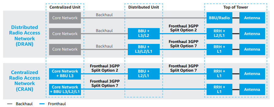
Choice of different options from a fully distributed to a fully centralized RAN architecture can address different requirements, offering the associated benefits (such as edge computing, high throughput at high mobility or centralized processing and simplified distributed coverage), within constraints (such as cost or transport requirements).
Ultimately, a flexible radio can address the service or operator requirements considering these trade-offs, potentially starting with a higher layer and a lower layer option.
Example of 5G DRAN deployment
Also in the White paper Exploring 5G Fronthaul Network Architecture Intelligence Splits and Connectivity by Intel, there’s a good example for 5G DRAN deployment as below:
This 5G DRAN deployment example shows an architecture using either an option 2 or option 7 extensible Radio Access Network (xRAN) split for sub-6 GHz, where the DU can be at or near the antenna site. The DU connects to RRHs that could be anywhere from a few meters to 10 km from the DU, and the BBU/RRH workloads are split accordingly.
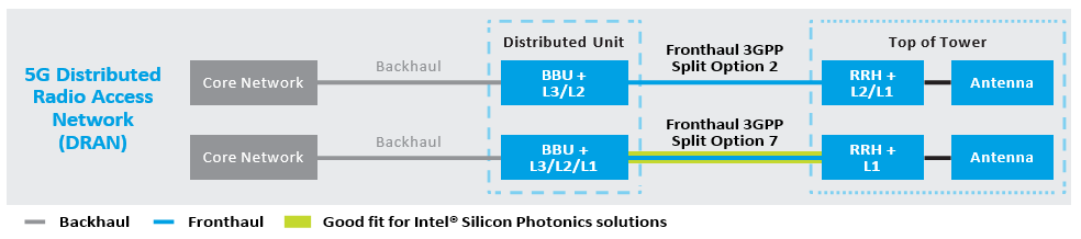
If a bandwidth of 100 MHz using a sub-carrier spacing (SCS) of 60 kHz is assumed, then a 3-sector antenna using a single carrier with a 4×4 antenna arrangement would require around 34 Gbps fronthaul capacity across an option 7 split, while an 8×8 arrangement would require around 67 Gbps. Note that the option 2 split fronthaul requirement capacity is much less, requiring a lower-capacity optical link.
| 5G Deployment | Bandwidth (BW) and Numerology | 3GPP Split Option 2 Fronthaul Rate Estimates | 3GPP Split Option 7 Fronthaul Rate Estimates |
| 5G: macro; 4×4 MIMO 3-sector, 1 carrier |
BW = 100 MHz SCS = 60 kHz (u=2) |
~4 Gbps | ~34 Gbps |
| 5G: macro; 8×8 MIMO 3-sector, 1 carrier |
BW = 100 MHz SCS = 60 kHz (u=2) |
~8Gbps | ~67Gbps |