In the high-level network architecture, the RAN is represented as a single functional entity whereas in reality the realization of a 5G RAN is not so straightforward.
In GSM/GPRS and UMTS there was a network controller [BSC and RNC] which provided an interface between the radio access network and the core network. This network controller hid a lot of signaling from the core, particularly in UMTS, and managed a range of complex RAN functions. In LTE there is no network controller, the RAN manages a range of mobility management and radio optimization activities between evolved Node Bs via the X2 interface.
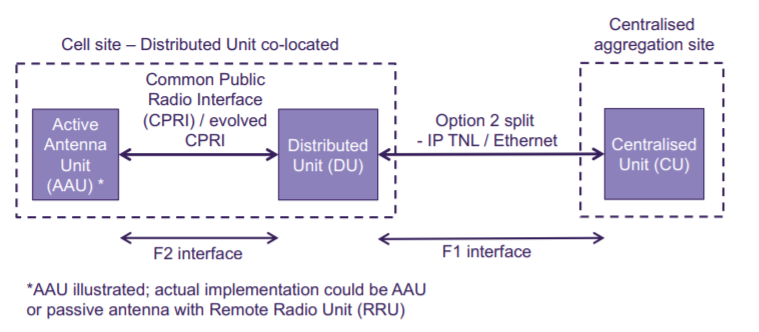
5G effectively introduces a centralized RAN node albeit not a network controller as such. The 5G radio base station, known as next Generation Node B (gNB) is split into two entities: a gNB-Distributed Unit (gNB DU (often shortened to DU)) and a gNB-Centralized Unit (gNB-CU (often shortened to CU)).
RAN Split Protocol Architecture
3GPP used the RAN protocol model as per below figure (3GPP TR 38.801) to discuss the functional split which should be implemented in 5G. Note that this protocol model is based on LTE as this was all that was known at the time although this
doesn’t differ significantly from 5G NR.
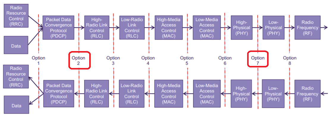
The same terms are used although there have been some minor movements of functional sub-entities. Additionally, a new protocol, known as Service Data Adaptation Protocol (SDAP), has been introduced to the NR user plane to handle flow-based Quality of Service (QoS) framework in RAN, such as mapping between QoS flow and a data radio bearer, and QoS flow ID marking.
Reading the above figure from left to right,
- Radio Resource Control (RRC) resides in the control plane while the data is user plane.
- SDAP will be inserted between data and the Packet Data Convergence Protocol (PDCP) for a standards-compliant 5G NR view of the protocol stack. Functions of PDCP include; IP header compression and decompression along with ciphering and deciphering (encryption of the data over the radio interface). PDCP feeds down the stack to the Radio Link Control (RLC) layer.
- RLC functions include; Error correction with Automatic Repeat request (ARQ), concatenation and segmentation, in sequence delivery and protocol error handing.
- Moving down the stack from RLC to the Medium Access Control (MAC) layer we find the following functions; multiplexing and de-multiplexing, measurement reports to RRC layer, Hybrid ARQ error correction, scheduling and transport format selection.
- The Physical Layer takes care of the actual radio waveform and modulation scheme, amongst other things.
Which Split is Appropriate ?
After much debate 3GPP agreed on an Option 2 functional split, meaning that PDCP and therefore everything above this layer will reside in the CU while RLC and everything below it will reside in the DU. This is known as a higher layer split given its location within the protocol stack.
The interface between the CU and DU has been designated “F1” as per below figure; this will be supported by an IP transport network layer which will be carried over an underlying Carrier Ethernet network. Given the chosen location of the functional split there are no exacting latency requirements on the F1 interface; in fact it’s likely that the latency constraints applied to the F1 interface will be derived from the target service based latency.

The data rate required for the option 2 F1 interface is very similar to that of traditional backhaul (LTE S1 interface as a reference) for a given amount of spectrum multiplied by the improved spectral efficiency of NR.
In the case of the HLS split, the E1 and F1 interfaces may get exposed either physically on the cell sites or on the network side, especially if the network uses resources from different security domains. The threats depend on particular split configurations and implementations of the interfaces.
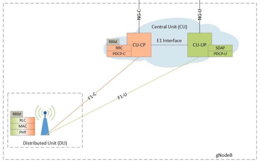
In split option 2, the PDCP protocol, specified in 3GPP TS 38.323, is executed in CU and enables the protection of the User Plane and Control Plane confidentiality and integrity (including anti-replay) on the F1 interface. More precisely, there is a separation between the Control Plane (CP) traffic on F1-C and User Plane (UP) traffic on F1-U, with the protection by PDCP-C and PDCP-U.
References:
- 5G RAN CU – DU Network Architecture, Transport Options and Dimensioning v 1.0
- 5G NETWORK ARCHITECTURE by ANDY SUTTON