
The uplink challenge is inherent to deployments that rely primarily on mid-band TDD spectrum. Most 5G capacity relies on mid-band TDD spectrum near 3.5 GHz, which presents three main uplink limitations. First, smartphones transmit at much lower power than base stations, resulting in reduced uplink coverage compared to downlink. Second, higher frequencies experience higher path loss and poorer penetration, reducing practical uplink coverage, so a 3.5 GHz uplink covers less area than an 1800 MHz uplink. Third, TDD frame structures prioritize the downlink; many commercial deployments use DL-heavy TDD patterns such as DDDSU, where uplink opportunities are much less frequent than downlink. The device has only one uplink slot for every five downlink slots.
These limitations were less significant when most mobile traffic was downlink. However, with the rise of video calling, social video uploads, cloud gaming, and interactive applications, uplink performance has become a critical bottleneck. Users at the cell edge experience 5G degradation in uplink first.
What SUL does
Supplementary Uplink (SUL), standardized by 3GPP in Release 15, pairs a mid-band TDD carrier with a second, low-band carrier that exists only for uplink. The device transmits on one carrier or the other in any given slot — never both simultaneously. That per-slot switching is what separates SUL from uplink carrier aggregation, where carriers transmit in parallel.
The spectrum for these uplink-only carriers is not new. 3GPP re-used the uplink halves of existing FDD bands and assigned them SUL band numbers in TS 38.101-1. The clearest example: 1710–1785 MHz serves as both the uplink of FDD band n3 and the standalone SUL band n80. The paired 1800 MHz downlink continues operating in FDD as before, so nothing is sacrificed on the downlink side.
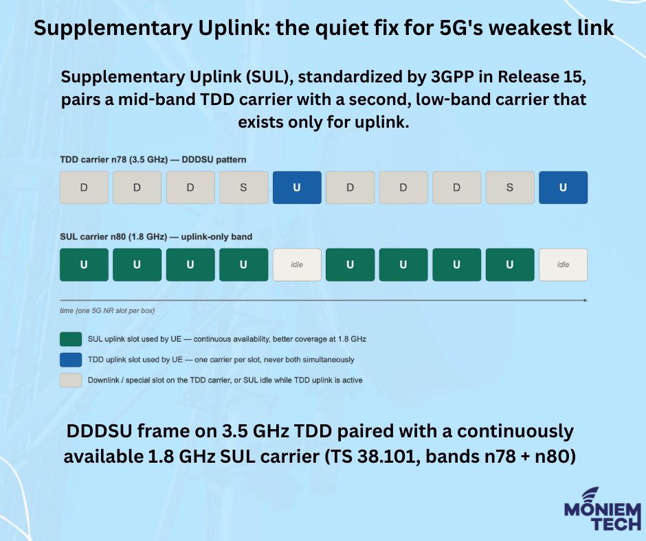
When paired with a 3.5 GHz TDD carrier (n78), a sub-3 GHz SUL band addresses all three uplink challenges simultaneously:
Coverage: At 1800 MHz, the uplink link budget extends significantly further than at 3.5 GHz. Users at the cell edge who cannot maintain a 3.5 GHz uplink can switch to the low band and remain on 5G, avoiding a degraded experience. The network selects the carrier based on a downlink signal strength threshold (The network configures an SSB RSRP threshold (rsrp-ThresholdSSB-SUL) that helps determine when the UE should access the SUL carrier): below the threshold, the device uses SUL; above it, the standard uplink.
Latency: Because SUL uses a dedicated uplink carrier, uplink transmissions do not need to wait for the next uplink slot on the TDD carrier, reducing scheduling delay in many deployments.
Capacity and consistency: A dedicated uplink carrier reduces dependence on the TDD carrier’s limited uplink opportunities, improving uplink consistency.
What SUL does not do
SUL is a coverage and latency tool, not a peak-speed tool. Because the device toggles between carriers rather than combining them, SUL does not increase uplink throughput as uplink carrier aggregation does. Operators chasing headline uplink speeds deploy UL CA or additional TDD uplink slots; operators chasing uplink consistency at the cell edge deploy SUL. The two are complementary, and 3GPP band combinations allow both.
Deployment has also been geographically lopsided. SUL has seen its widest commercial use in China, where operators paired 2.1 GHz and 1800 MHz uplink spectrum with 3.5 GHz and 2.6 GHz TDD carriers, and where the concept evolved into the “uplink-centric” pillar of the 5G-Advanced roadmap. Elsewhere, most operators have preferred carrier aggregation, EN-DC uplink fallback to LTE, or simply denser grids — partly because SUL requires device-side support for the specific SUL band combination, and the device ecosystem outside China has been thinner. Any assessment of SUL’s real-world impact needs to start from the reality of adoption rather than the standard’s elegance.
Why it shows up in user experience data
For measurement and benchmarking, SUL’s signature is distinctive: it lifts the floor of uplink experience rather than the ceiling. Networks with effective low-band uplink strategies — whether via SUL, low-band NR carriers, or aggressive spectrum refarming — tend to show tighter uplink speed distributions and better consistency at the edges of coverage, even when their headline uplink averages look unremarkable. As uplink-heavy applications keep growing, that floor is increasingly the line between a usable 5G experience and a frustrating one.
SUL is primarily intended for users near the edge of coverage, while users with strong mid-band signals typically continue transmitting on the normal uplink carrier.
What is the difference between SUL, UL CA, and UL Switching?
Sources
- 3GPP TS 38.300 — NR and NG-RAN overall description (Supplementary Uplink clause and Annex B.1)
- 3GPP TS 38.101-1 — UE radio transmission and reception, FR1 (SUL band definitions, Table 5.2-1)
- 3GPP TS 38.321 — MAC protocol specification (SUL carrier selection at random access)
- 3GPP TS 38.331 — RRC protocol specification (supplementary uplink configuration)
- 3GPP TS 38.213 — Physical layer procedures for control (uplink power control with NUL/SUL)
- NGMN Alliance — 5G TDD Uplink White Paper v1.0 (2022)