The next mobile cell site may not stand on a rooftop, tower, or mountain ridge. It may fly in the stratosphere.
High Altitude Platform Stations, or HAPS, are emerging as a practical way to extend mobile coverage directly to ordinary devices in areas where terrestrial networks are unavailable, uneconomic, or disrupted. However, turning a stratospheric platform into a commercial RAN layer requires far more than lifting an antenna into the sky. It demands a complete rethinking of radio planning, payload architecture, interference coexistence, feeder-link resilience, and mobile-core integration.
In this article, I use D2D to mean Direct-to-Device, but it is important to clarify the terminology. Historically, D2D has also referred to Device-to-Device communications, where terminals communicate directly with each other without relying on cellular infrastructure. In that model, wireless terminals can form local ad hoc networks using autonomous discovery, distributed synchronization, and direct communication, which can be useful for disaster resilience and local information exchange.
In the HAPS context, however, D2D refers to Direct-to-Device communication, where ordinary mobile devices connect directly to a non-terrestrial network node, specifically a High Altitude Platform Station. This article focuses on Direct-to-Device mobile service via HAPS, based on NTT DOCOMO’s presentation and technical direction at MWC 2025.
System objective
The engineering goal is to build an extreme-coverage extension layer above terrestrial mobile networks.
NTN/HAPS concept targets places where terrestrial RAN deployment is weak, damaged, uneconomic, or physically impossible: mountainous regions, remote islands, maritime zones, airspace, disaster areas, ships, drones, and other non-terrestrial or low-density coverage areas. So HAPS can be part of the 5G evolution and 6G-era coverage across air, sea, and space.
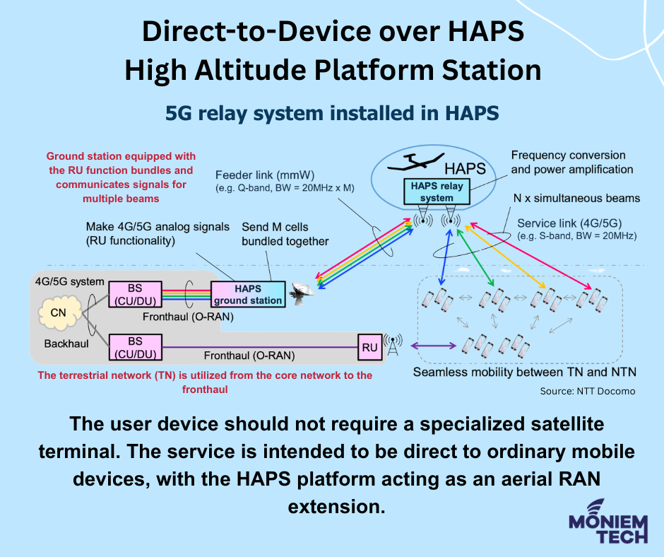
The basic service model is:
standard UE / smartphone → HAPS service link → HAPS payload → feeder link → terrestrial gateway / satellite backhaul → mobile core
The key point is that the user device should not require a specialized satellite terminal. The service is intended to be direct to ordinary mobile devices, with the HAPS platform acting as an aerial RAN extension.
High-level architecture
A HAPS-based Direct-to-Device network contains three main link domains.
1. Service link
The service link is the radio interface between the user equipment and the HAPS payload. This is the most constrained part of the system because the UE has limited transmit power, small antenna gain, and battery constraints. Unlike a terrestrial macro site, the HAPS node is positioned in the stratosphere, so link budget, beam design, propagation delay, Doppler behavior, and interference coordination must be reconsidered.
2. HAPS payload
The HAPS payload can be implemented in two broad ways:
- Transparent payload
The platform behaves primarily as a radio relay. It repeats and amplifies signals between the UE and the ground network. - Regenerative payload
The platform hosts more base-station functionality onboard, such as eNB/gNB functions. In this mode, the HAPS is closer to a flying base station than a simple relay.
3. Feeder link
The feeder link connects the HAPS platform to the ground network or to a satellite backhaul path. In general, the mobile operator is responsible for feeder-link control technologies, such as site diversity and transmit-power control, while the satellite operator is responsible for satellite and multi-gateway network integration.
This distinction matters because a HAPS system is only useful if its service-link coverage is backed by a robust transport path. A high-quality air interface is insufficient if the feeder link is capacity-limited or unavailable.
Payload architecture: transparent versus regenerative
1. FDD transparent payload
In the FDD transparent approach, the HAPS payload operates largely as a relay. It receives radio signals from one side, amplifies or frequency-translates them if required, and forwards them to the other side. Much of the RAN intelligence remains on the ground.
This architecture offers several advantages. Because the HAPS platform primarily serves as a relay, it requires lower onboard processing complexity, thereby reducing payload weight, power consumption, and thermal-management requirements. It also allows easier integration with ground-side base-station infrastructure, since most core RAN functions remain on the ground. As a result, lifecycle management becomes simpler, and early deployment may be faster compared with a fully regenerative HAPS architecture. However, transparent payloads also have limitations. Since the HAPS does not fully terminate radio protocols onboard, service performance becomes more dependent on feeder-link quality and propagation delay. In addition, noise and interference may be relayed together with the useful signal, making RF design, filtering, and link-budget control critical to overall system performance.
Technically, this makes the transparent architecture attractive for early service-link extension, especially where the operator wants to reuse existing terrestrial RAN assets.
2. TDD regenerative payload
In the TDD regenerative approach, the HAPS payload includes base-station functions such as eNB/gNB. This means the radio link can be terminated or partly processed onboard before traffic is forwarded through the feeder network.
The regenerative model is more complex but offers greater architectural flexibility. In this approach, the HAPS can operate more like an autonomous aerial cell site, with base-station functions hosted onboard rather than relying entirely on ground-side processing. This allows radio scheduling to be performed closer to the UE and can reduce dependence on a local gateway within the coverage footprint. It also makes satellite backhaul more practical, since the HAPS can process and manage radio traffic before forwarding it through the transport network. With more onboard intelligence, the system can also handle interference coordination, mobility behavior, and service continuity more effectively than a purely transparent relay architecture.
This is technically important because TDD introduces timing and interference issues that differ from those in FDD. A HAPS cell may cover a very wide footprint, and uplink/downlink switching patterns must be engineered so that HAPS transmissions do not collide with terrestrial cells or neighboring beams.
Radio interface engineering
1. Link budget
The most difficult D2D-over-HAPS constraint is the UE-to-HAPS uplink.
A terrestrial site can rely on elevated antennas, high-gain sector panels, and a relatively short cell radius compared with a stratospheric HAPS platform. A smartphone, however, operates with limited maximum transmit power, low antenna gain, body and orientation losses, battery constraints, thermal limits, and limited ability to compensate for long propagation paths. As a result, the HAPS service link must be carefully engineered using high-gain antenna systems on the platform, narrow or semi-narrow beams, optimized cell-footprint design, robust modulation and coding, beam-level interference management, adaptive power control, and potentially lower-order MCS for cell-edge, maritime, or other challenging coverage scenarios.
The practical design target is not just peak throughput. It is a minimum viable service continuity across areas where terrestrial mobile coverage is absent or impaired.
2. Beam and footprint design
A HAPS platform can cover a large geographic area, but the system must divide that coverage into beams or cells. The configurations can use 4 to 16 beams/cells and footprint-shape optimization.
Beam design has several technical objectives:
- Maximize useful coverage
The beam footprint should cover target gaps such as maritime corridors, remote islands, mountain valleys, or disaster zones. - Minimize terrestrial overlap
Overlap with terrestrial gNBs can create co-channel or adjacent-channel interference. - Control uplink interference
A broad HAPS receive beam may be subject to interference from many terrestrial UEs or cells. - Enable frequency reuse
Multiple beams require a reuse plan to prevent adjacent or overlapping beams from degrading the SINR. - Support mobility
Users, drones, ships, and aircraft may move through beam boundaries differently from terrestrial users moving across macro cells.
Frequency reuse and coexistence with terrestrial RAN
The most important RAN-planning issue for HAPS deployment is coexistence with terrestrial 4G and 5G networks. A HAPS beam may illuminate areas that are already served by terrestrial base stations, creating interference risks if both systems operate on the same or adjacent spectrum without coordination. Potential interference scenarios include HAPS downlink interference into terrestrial UEs, terrestrial gNB downlink interference into HAPS-served UEs, terrestrial UE uplink interference received by the HAPS payload, and HAPS-attached UE uplink interference into terrestrial gNBs. Additional challenges can also arise from inter-beam interference between neighboring HAPS cells and cross-link interference in TDD deployments, where uplink and downlink transmissions are not properly aligned across different network layers.
For this reason, frequency reuse becomes a central design mechanism rather than a secondary optimization. Operators cannot treat HAPS as a simple high-altitude macro cell; instead, they need an integrated 3D frequency plan that accounts for terrestrial cells, HAPS beams, gateway beams, and potentially satellite backhaul. In practice, this plan may include dedicated HAPS spectrum where available, partial frequency reuse across HAPS beams, exclusion zones near terrestrial macro cells, adaptive beam muting, dynamic spectrum partitioning, TDD pattern coordination, and uplink power-control constraints for HAPS-attached UEs. DOCOMO’s work on Band 34/n34 is relevant in this context because using relatively underutilized spectrum can reduce interference pressure on existing commercial terrestrial layers.
FDD versus TDD in HAPS D2D
1. FDD characteristics
FDD separates uplink and downlink into paired frequency bands. For HAPS, this can simplify duplexing and avoid some uplink/downlink timing collisions.
FDD advantages:
FDD provides predictable separation between uplink and downlink because each direction uses a dedicated frequency band. This makes it easier to integrate with legacy mobile architectures, since many existing cellular systems already rely on paired-spectrum operation. It also reduces the need for tight TDD frame synchronization, lowering the risk of uplink/downlink timing conflicts. As a result, FDD can be a more straightforward option for transparent HAPS relay implementation, where the platform primarily repeats or amplifies signals rather than performing full onboard base-station processing.
FDD disadvantages:
FDD also has important limitations. It requires a paired spectrum, meaning separate frequency resources must be available for uplink and downlink. This can make spectrum allocation more difficult, especially in bands where paired resources are scarce or already heavily used. Because the uplink and downlink channels are fixed, FDD offers less flexibility in adjusting capacity to match traffic demand. This can reduce efficiency for asymmetric services, where downlink traffic is much heavier than uplink traffic. In a HAPS system, FDD may also make feeder-link and service-link planning more spectrum-intensive, since the operator must reserve and coordinate separate frequency resources across multiple beams, gateways, and coverage areas.
FDD transparent mode is, therefore, a logical early architecture when the priority is coverage extension with lower payload complexity.
2. TDD characteristics
TDD uses the same frequency band for uplink and downlink, with the two separated in time. This is attractive where an unpaired spectrum is available, such as n34, but it creates tighter timing requirements.
TDD advantages:
TDD offers greater flexibility because uplink and downlink transmissions share the same frequency band and are separated in time. This allows the network to dynamically adjust the uplink/downlink ratio according to traffic demand, which is useful for services with highly asymmetric data patterns. TDD also supports unpaired spectrum, making it attractive in bands where paired FDD spectrum is unavailable or difficult to allocate. In the context of HAPS and NTN, TDD may be especially relevant for future 5G and 6G integration, since it can support flexible spectrum use, adaptive traffic handling, and more efficient use of available frequency resources in certain bands.
TDD disadvantages:
TDD also introduces additional engineering complexity. Because uplink and downlink transmissions use the same frequency band at different times, the network requires careful synchronization or sufficient isolation between cells, beams, and neighboring systems. Without proper coordination, TDD deployments are vulnerable to cross-link interference, where one node is transmitting downlink while another nearby node is expecting uplink reception. In a HAPS environment, this problem becomes more challenging because the long propagation distance affects timing advance, frame alignment, and guard-period design. The wide HAPS footprint can also expose the system to more terrestrial cells, user devices, and adjacent beams, increasing the number of potential interference sources that must be managed.
In a HAPS environment, asynchronous TDD may be operationally flexible but harder to protect from interference. Synchronous TDD may reduce cross-link interference but imposes tighter coordination constraints across terrestrial and aerial layers.
Feeder-link engineering
The HAPS feeder link is the transport path between the airborne platform and the rest of the network. It can be terrestrial-gateway based, satellite-backhauled, or a hybrid of both.
1. Site diversity
Site diversity means using multiple gateway stations so that the HAPS can maintain connectivity even if one gateway is degraded by weather, blockage, congestion, maintenance, or damage from disasters. This is particularly important because the use cases include disaster recovery. A HAPS platform covering a disaster zone should not depend on a single gateway that may itself be affected by the disaster.
2. Transmit-power control
Feeder-link transmit-power control is required to maintain link quality while avoiding unnecessary interference or energy consumption. HAPS platforms have strict power budgets, especially if solar-powered, so RF power must be managed carefully.
3. Satellite backhaul
Satellite backhaul becomes important when no suitable terrestrial gateway is available within or near the HAPS coverage area. The IEICE summary notes that satellite backhaul for regenerative payloads can enable HAPS operation without installing a ground gateway inside the coverage area. This is especially relevant for maritime, island, mountain, and disaster scenarios.
Mobility and network control
HAPS mobility differs from both terrestrial RAN and LEO satellite NTN. A terrestrial cell tower is fixed, while a LEO satellite moves rapidly relative to the user. A HAPS platform sits between these two models: it is quasi-stationary, but not perfectly fixed. It may drift, circle, or reposition to maintain station-keeping, which means its beam footprints can shift gradually over time. This creates a distinct mobility-control problem, in which handovers may occur not only between terrestrial cells but also between HAPS beams and potentially satellite layers. Although Doppler effects are generally lower than in LEO systems, they are not always negligible, and timing advance still needs to account for long slant ranges between the UE and the HAPS platform. As the platform position changes, location-dependent interference conditions may also change across the served area.
For commercial deployment, the operator therefore needs robust mobility and access-control policies. These include terrestrial-to-HAPS reselection, HAPS-to-terrestrial fallback, HAPS beam-to-beam mobility, emergency attach behavior, priority access during disasters, and specific mobility profiles for maritime and airborne users. In practice, the HAPS layer should not be treated as a conventional macro layer. It is better modeled as an overlay coverage layer with dedicated access, reselection, handover, and prioritization rules that reflect its wide footprint, long propagation path, and role as an extreme-coverage extension layer.
Core-network integration
Technical challenges before commercialization
Conclusion
D2D via HAPS is a non-terrestrial RAN overlay that extends mobile coverage beyond the limits of terrestrial infrastructure. It enables ordinary devices to connect directly to a stratospheric platform, supporting coverage in remote, maritime, airborne, mountainous, and disaster-affected areas.
The architecture may use a transparent payload for simpler relay-based deployment or a regenerative payload for more autonomous onboard base-station functionality. Each option introduces different trade-offs in complexity, power, spectrum use, feeder-link dependency, and network control.
Ultimately, HAPS is not just a “cell tower in the sky.” It is a 3D, multi-link NTN system that requires careful engineering across link budget, beam design, interference coexistence, mobility, backhaul, and core-network integration.